
Mark-10 Corporation (2017) User’s guide to ESM 303 force test stand. J Achievements Mater Manuf Eng 34(2):145–151 Mar NSS, Fookes C, Yarlagadda PKDV (2009) Design of automatic vision-based inspection system for solder joint segmentation. Harris PG, Chaggar KS (1998) Role of intermetallic compounds in lead-free soldering. Originally published in the SMTA proceedingsįlanagan K (2018) Stages of a reflow profile: part III. Jetting solder paste opens up new possibilities in your SMT production. APEX, Anaheim CAīuetow M (2015) Solder fatigue led to AirAsia crash, investigators say.

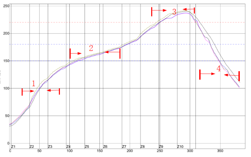
Global SMT Packag Mag 16(12):14–18ījorn D, Lasky RC (2004) Optimizing your reflow profile for maximum productivity and profitability. Application note: 81, vol 81, no 4, pp 1–10īaluch D, Minogue G (2007) Fundamentals of solder paste technology. KeywordsĪltera Corporation (2008) Reflow soldering guidelines for surface-mount devices. A total of 45 live cases under 22 groups is presented. The methods for mitigation/elimination of these defects have also been explained. The defect due to presence of flux residues has also been touched upon. Formation of solder bumps, solder balls, cold joints and the tombstoning defect have been discussed. The defects on soldering of chip resistors, chip capacitors, surface mounted integrated circuits, OSM connectors, jumper wires and other defects have been captured, and all have been illustrated with high resolution photographic images. The guidelines formulated for production flow of electronic packages based on detailed experiments and validation have been tabulated. It describes the general flux formulations and the reflow profile. It touches upon the classification of solder wetting correlating to the dihedral angle of wetting. To obtain higher quality and reliability of solder joints, reflow time-temperature curve has to be reset so that SAC solder balls can be completely melted and lead in SnPb solder paste can be absolutely mixed with melted SAC solder balls.This chapter addresses the importance of soldering and describes briefly the sequence of events occurring during the soldering operation. As a result, the solder joints are uneven and unstable. How far lead can be dissipated in SAC solder balls depends on how high reflow temperature is set and how soon SnPb solder will be melted in solder paste. Lead will be dissipated to the boundary of solder ball crystal particles that are not totally melted. Solder paste (SnPb) coated on pad is melted but SAC solder balls are still not melted. When lead-free solder needs to be cooperated with lead solder paste, backward compatibility will happen. As a result, vacancies and internal non-metal slag inclusions will be generated due to difficult expelling of flux solvent and contaminant in solder paste, which are not allowed. In this situation, BGA solder joints are melted first and covered on solder paste whose alloy isn't melted, leading to massive collapse and oxidation of lead solder balls. As a result, soldering defects tend to be caused in this transient process.įor example, when lead-free SAC solder paste is used to solder lead BGA (ball grid array) solder joints, forward compatibility will take place, which derives from the fact that component distributors' lead-free schedule is later than that of PCB manufacturers'. That's because different apartments in electronics manufacturing industries fail to keep synchronization on lead-free schedule and technology preparation. A transient process must be available with lead and lead-free elements coexisting. Total transition can never be achieved just by one step from complete SnPb soldering system to totally lead-free soldering system. As a result, all the soldering tools manufactured by industrial manufacturers, soldering equipment and supporting materials used for soldering have to be designed and selected based on heat resistance of 260☌. Peak temperature in lead-free reflow soldering can be as high as 250☌, so the lowest heat resistance of MVCs has to be set to be at least 260☌. Lead and lead-free components differ from each other in terms of their capability to withstand reflow soldering.īecause the peak temperature in lead reflow soldering won't exceed 230☌, heat resistance of MVCs should be set to be at 240☌, including all the soldering tools manufactured by industrial manufacturers, soldering equipment and supporting materials used for soldering all of which are designed and selected based on heat resistance of 240☌. MVCs refer to the most vulnerable components (MVCs) during reflow soldering such as liquid dielectric aluminum electrolytic capacitors, connectors, DIP switches, LEDs, transformers, PCB (Printed Circuit Board) substrate material etc.


 0 kommentar(er)
